Types and performance evaluation, efficient system operation, Flow control strategies and energy saving opportunities, Assessment of cooling towers
Cooling towers are a very important part of many chemical plants. The primary task of a cooling tower is to reject heat into the atmosphere. They represent a relatively inexpensive and dependable means of removing low-grade heat from cooling water. The make-up water source is used to replenish water lost to evaporation. Hot water from heat exchangers is sent to the cooling tower. The water exits the cooling tower and is sent back to the exchangers or to other units for further cooling.
Cooling tower types
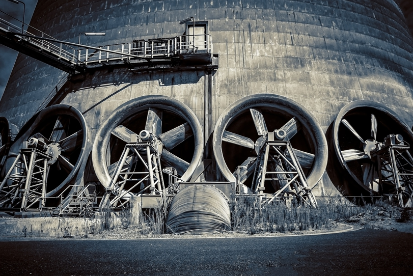
Cooling towers fall into two main categories: Natural draft and Mechanical draft. Natural draft towers use very large concrete chimneys to introduce air through the media. Due to the large size of these towers, they are generally used for water flow rates above 45,000m3/hr. These types of towers are used only by utility power stations.
Mechanical draft towers utilise large fans to force or suck air through circulated water. The water falls downward over fill surfaces, which help increase the contact time between the water and the air – this helps maximise heat transfer between the two. Cooling rates of Mechanical draft towers depend upon their fan diameter and speed of operation.
Components of Cooling Tower
The basic components of an evaporative tower are: Frame and casing, fill, cold water basin, drift eliminators, air inlet, louvers, nozzles and fans.
Frame and casing
Most towers have structural frames that support the exterior enclosures (casings), motors, fans, and other components. With some smaller designs, such as some glass fibre units, the casing may essentially be the frame.
Fill
Most towers employ fills (made of plastic or wood) to facilitate heat transfer by maximising water and air contact. Fill can either be splash or film type. With splash fill, waterfalls over successive layers of horizontal splash bars, continuously breaking into smaller droplets, while also wetting the fill surface. Plastic splash fill promotes better heat transfer than the wood splash fill.
Cold water basin
The cold water basin located at or near the bottom of the tower, receives the cooled water that flows down through the tower and fills. In some forced draft counter flow design, however, the water at the bottom of the fill is channelled to a perimeter trough that functions as the cold water basin. Propeller fans are mounted beneath the fill to blow the air up through the tower. With this design, the tower is mounted on legs, providing easy access to the fans and their motors.
Drift eliminators
These capture water droplets entrapped in the air stream that otherwise would be lost to the atmosphere.
Air inlet
This is the point of entry for the air entering a tower. The inlet may take up an entire side of a tower–cross flow design– or be located low on the side or the bottom of counter flow designs.
Louvers
Generally, cross-flow towers have inlet louvers. The purpose of louvers is to equalise air flow into the fill and retain the water within the tower. Many counter flow tower designs do not require louvers.
Nozzles
These provide the water sprays to wet the fill. Uniform water distribution at the top of the fill is essential to achieve proper wetting of the entire fill surface. Nozzles can either be fixed in place and have either round or square spray patterns or can be part of a rotating assembly as found in some circular cross-section towers.
Fans
Both axial (propeller type) and centrifugal fans are used in towers. Generally, propeller fans are used in induced draft towers and both propeller and centrifugal fans are found in forced draft towers. Depending upon their size, propeller fans can either be fixed or variable pitch.
Factors Affecting Cooling Tower Performance
Capacity
Heat dissipation (in kCal/hour) and circulated flow rate (m3/hr) are not sufficient to understand cooling tower performance. Other factors, which we will see, must be stated along with flow rate m3/hr. For example, a cooling tower sized to cool 4540 m3/hr through a 13.9°C range might be larger than a cooling tower to cool 4540 m3/hr through 19.5°C range.
Range
Range is determined not by the cooling tower, but by the process it is serving. The range at the exchanger is determined entirely by the heat load and the water circulation rate through the exchanger and on to the cooling water.
Range °C = Heat Load in kCals/hour/Water Circulation Rate in LPH
Thus, Range is a function of the heat load and the flow circulated through the system. Cooling towers are usually specified to cool a certain flow rate from one temperature to another temperature at a certain wet bulb temperature. For example, the cooling tower might be specified to cool 4540 m3/hr from 48.9°C to 32.2°C at 26.7°C wet bulb temperature.
Function of Fill media in a Cooling Tower
Heat exchange between air and water is influenced by surface area of heat exchange, time of heat exchange (interaction) and turbulence in water effecting thoroughness of intermixing. Fill media in a cooling tower is responsible to achieve all of above.
Splash and Film Fill Media:
As the name indicates, splash fill media generates the required heat exchange area by splashing action of water over fill media and hence breaking into small- er water droplets. Thus, surface of heat exchange is the surface area of the water droplets, which is in contact with air.
Film Fill and its Advantages
In a film fill water forms a thin film on either side of fill sheets. Thus area of heat exchange is the surface area of the fill sheets, which is in contact with air.
Due to fewer requirements of air and pumping head, there is a tremendous saving in power with the invention of film fill.
Recently, low-clog film fills with higher flute sizes have been developed to handle high turbid waters. For sea water, low clog film fills are considered as the best choice in terms of power saving and performance compared to conventional splash type fills. |
Efficient System Operation
Cooling Water Treatment
Cooling water treatment is mandatory for any cooling tower whether with splash fill or with film type fill for controlling suspended solids, algae growth, etc.
With increasing costs of water, efforts to increase Cycles of Concentration (COC), by Cooling Water Treatment would help to reduce make up water requirements significantly. In large industries, power plants, COC improvement is often considered as a key area for water conservation.
Drift Loss in the Cooling Towers
It is very difficult to ignore drift problem in cooling towers. Now-a-days most of the end user specification calls for 0.02 percent drift loss.
With technological development and processing of PVC, manufacturers have brought large change in the drift eliminator shapes and the possibility of making efficient designs of drift eliminators that enable end user to specify the drift loss requirement to as low as 0.003 – 0.001 percent.
Cooling Tower Fans
The purpose of a cooling tower fan is to move a specified quantity of air through the system, overcoming the system resistance which is defined as the pressure loss. The product of air flow and the pressure loss is air power developed/work done by the fan; this may be also termed as fan output and input kW depends on fan efficiency.
For more information, visit:
www.beeindia.gov.in
Cookie Consent
We use cookies to personalize your experience. By continuing to visit this website you agree to our Terms & Conditions, Privacy Policy and Cookie Policy.


